Al's Robotics....
| Site
Index |
| Site Index |
| Rambo Auto Tools |
| Robotics Events |
| Linux Computing |
| Reading Books |
| Latest
News |
new information added to the Robux Project Pages click here for more info |

PIC Micro Robotics
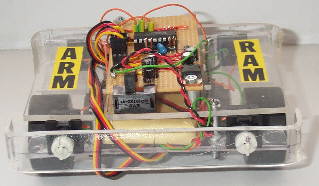
Look at the photos of ARM RAM.
ARM RAM is a PIC Micro controlled autonomous robot and Like KTX1, ARM RAM also has the ability to custom navigate it's surrounding with out any intervention by humans. But however there is one major difference, and that is how the servos are driven. On KTX1 the servo controller electronics were removed and replaced by H-Bridges but on ARM RAM the servo electronics are being fully utilised, so ARM RAM is even easier to build and costs less. It has all the sensors that KTX1 had and more. If you have all the PIC programming gear already then ARM RAM should cost you no more then about £35 to build.
Here are the things that you will need to build ARM RAM.
- Two modified servos (see my servo hacking tutorial to find out how)
- One chassis
- PIC Micro motherboard (with 4 MHz oscillator)
- Programmed PIC 16F84
- Two wheels
- And some sensors (momentary switches will do)
Sensors
The PIC sensor input pins should have a 4.7K resistor to +5 volts connected straight to the PIC Micro pin, and a monetary switch (sensor) that connects from - volts to the same PIC Micro pin (the switch/sensor should be permanently off until it is touched). The sensors should be set out in a similar fashion as can be seen on my robot in the photo section.

Sensor connection to the PIC Micro.
click here to see ARM RAMs full electronics circuit.
PIC connections
The sensor and servo connections to the PIC can be seen in the below drawing.
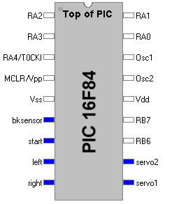
You can also see in the drawing that there is a "start" input, that is for a standard momentary switch the starts the robot once you have turned the power on and pressed the switch. see the chart below for details on the port connections i.e. the inputs and outputs.
| Lable
on PIC pin |
Discription
/ Connection |
| bksensor |
Sensor
input on back of robot (switch) |
| left
|
Sensor
input on the left side of the robot (switch) |
| right |
Sensor
input on the right side of the robot (switch) |
| servo1
|
Servo
output driver 1 for the left servo |
| servo2 |
Servo
output driver 2 for the right servo |
| start |
Robot
start up input switch |
The ARM RAM program.
Although this robot only has three sensors at the moment it will never get stuck in a corner or U shape, this is because of the advanced programming that I have done that monitors the sensors and if it finds that it is doing a repetitive task with in a set time it will stop and change it's direction. It is this that stops the robot from getting stuck in dead ends, corners and U shapes. There is actually four sensors on the robot but the two back sensors are connected up to the same PIC input port, while the two front sensors are independent but are linked to each other by the plastic bar. This is done so the robot can detect obstacles to the front left, front right and in the middle (note that if the right or left side is hit/high it will not make the other side high, unless the bar is hit in the middle).
As time goes on I plan to add more sensors to ARM RAM so keep checking to see if I have changed the system. Sensors that are on the agenda to be added are tilt sensors, floor sensors, light sensors and even ranging systems to eliminate the switch sensors I will probably use infra red for this oh and a communications system so if two or more robots are made with ARM RAM code on they will be able to talk to each other ( cool hey ).
Get the PIC code
The PIC code is available here free of charge to any one that wants to use it so long as you DON'T copy and sell it. I do not take any responsibility for the software (PIC code) so if it blows up your PIC and burns down your house don't blame me. There is a lot of files in the win zip file and you will need them all. ideally you should use wizpic (click here to get it) to open the files and program it into your PIC but if you go threw the files you will find one that your pic programmer software will like (I use the "ARMRAM~1.HEX" file)
If you download and use the ARM RAM PIC code I would like to have your comments and views on it so I can get some feedback.
Thanks.
Web pages built and © by A R Martin E-mail at:
Home-page Robots Tutorials Links E-mail Circuits Events BEAM PIC Microchip Robotics Shop Computers FMM-RobotWars Sponsors Suggested reading Ebay Listings Serial Speed Controllers MicroMouse Walkers Driller-Killer Laptops Excaliber Robot Retox Drill Robot Robot motors Robot Builder Google Robux Project gorobotics Robot Cafe Robotics Solar Navigator PIC Axe Tech Supplies MUTR GSM Control Home Automation RC tracker Qtronics Design - Electronics & Firmware Design Artist R C Martin http://www.speedace.info/qtronics.htm http://www.solarnavigator.net/qtronics.htm http://www.elecdir.com/site/store/23197/index.html http://www.robotbuilder.co.uk/forum/topic.asp?whichpage=2&TOPIC_ID=861ᶱ